
DIY Panel Drying Rack
Woodworking · CNC & hand-tool build
Design preview: the first build is still ahead. Dimensions and fit are draft plans; measured cost, build photos and load testing will follow.
Walk around the design
Rotate the rack, hide the sample panels, or pull the assembly apart to see how it fits together.
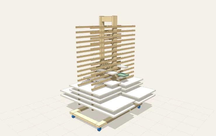 3D design illustration · not a finished build
Explore the model in 3D, or switch to the illustration. The plans and article below work without it.
Freshly painted plywood has a way of taking over every flat surface in the shop. This rolling drying rack is my answer: a simple 2×4 frame, rows of plywood arms, and small replaceable points that keep the wet finish off the wood.
I'm designing it for flat 3/4-inch plywood parts—drawer fronts, furniture panels, bed slats and similar pieces—while paint or stain dries. A CNC makes the repeated arms and housings straightforward. The same basic shapes can be cut and fitted with conventional woodworking tools.
The idea: spend less, keep the bench clear
The goal is to build a useful shop rack for significantly less than buying one. For comparison, the Rockler Mobile Finish Drying Rack was listed at $335.99 on sale when checked on October 14, 2026. That is the price target for this project, not a claim that these two racks have the same tested capacity.
My final materials total is still to come. It will include lumber, plywood, casters, hardware and filament. Already owning a CNC or having plywood offcuts changes the economics. I'll add actual costs after the build so the comparison is useful.
The rack at a glance
| Detail | Draft design |
|---|---|
| Base footprint | 30 × 50 inches |
| Overall height | About 73 inches, depending on casters |
| Storage layout | 17 levels, accessible from both sides |
| Arms | 46 inches long, reaching 23 inches in each direction |
| Bottom two levels | 1½-inch-tall plywood arms |
| Remaining 15 levels | 1-inch-tall plywood arms |
| Space between arms | 2¼ inches before the points and workpiece |
| Panel support | Two arms with four contact points per part |
There are 34 possible front/back positions, but part size determines how many can be used at once. This is for cut panels, not full 4×8 sheets. The intended panel depth is up to 24 inches; short pieces need a suitable tray spanning the arms. Thicker parts may need an empty level above them.
The base rolls on four locking casters. The arm-and-upright assembly is glued and screwed, while the base connection is intended to bolt together. The exploded model separates components to explain the construction; it does not mean every joint comes apart after assembly.
Shopping list
| What to buy | Quantity | Specification |
|---|---|---|
| 3/4-inch plywood | 1 sheet | 4 × 8 feet (48 × 96 inches), for the arms and gussets |
| 2×4 lumber | 5 boards | 8 feet long each, for the frame and base |
| Locking casters | 4 | Nominal 3-inch wheels, with mounting hardware |
| Wood glue | 1 bottle | For the frame, arm housings and gussets |
| Wood screws | 68 for the arms, plus frame/gusset screws | Draft calls for #8 × 1¼-inch screws at the arm joints |
| Base bolts and barrel nuts | Matching sets | For the frame-to-base connection; sizes and count pending |
| PLA filament | As needed | To print 136 contact points and one drill guide |
| 1/4-inch hardboard (optional) | Offcuts as needed | For 16 × 24-inch small-part trays; add separate finish-support points |
The first build will confirm the remaining hardware sizes and quantities, along with filament use.
Cut list
The layout files are based on nominal 3/4-inch plywood measured at 0.703 inches. Measure your own sheet before making joinery or using the drill guide. The supplied CNC nest uses almost the full length of a 48×96-inch sheet; do not assume all of these parts fit on an arbitrary half-sheet offcut.
| Part | Quantity | Size |
|---|---|---|
| Uprights, 2×4 | 2 | 68 inches |
| Long base rails, 2×4 | 2 | 50 inches |
| Cross rails, 2×4 | 4 | 23 inches |
| Stretchers, 2×4 | 3 | 10½ inches |
| Lower arms, 3/4-inch plywood | 4 | 46 × 1½ inches |
| Upper arms, 3/4-inch plywood | 30 | 46 × 1 inch |
| Foot gussets, 3/4-inch plywood | 4 | 7 × 7-inch triangular blanks |
Cutting with a CNC
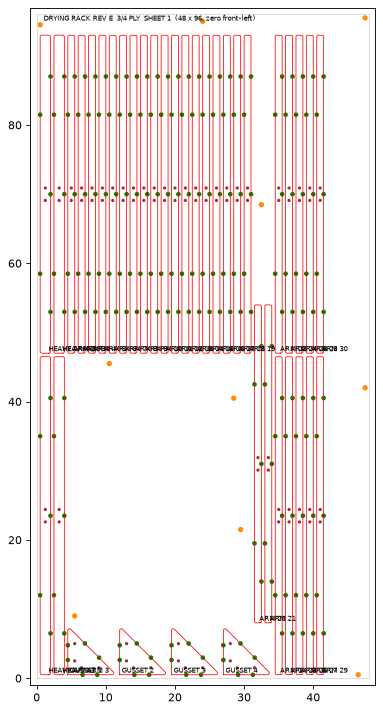
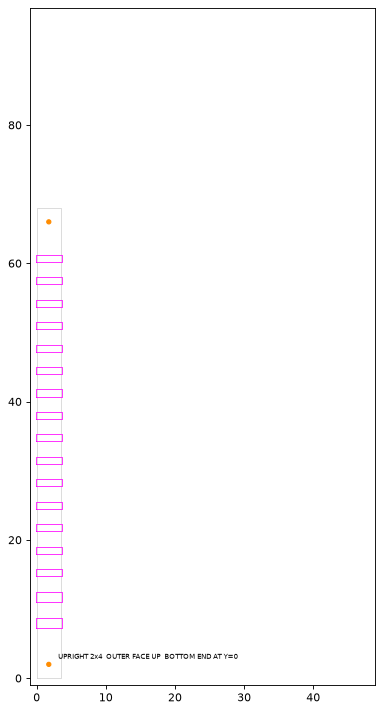
There are two DXF layouts: one for the arms and gussets, and one for the upright housings. The upright job is run twice. These are design files for preparing CAM, not ready-to-run G-code.
The 46-inch arm length lets two arms nest end to end along a sheet. Each upright has two 1.52-inch-tall lower housings and fifteen 1.02-inch-tall upper housings, all 3/8 inch deep. The extra 0.02 inch is the draft fit allowance. Cut one sample housing and test an actual arm before machining the full set.
Keep the bottom end of both uprights clearly marked so the two sets of housings line up. In your CAM software, verify units, measured stock thickness, tool diameters, workholding, tabs, cut depths and the machine origin. The supplied layout previews show the intended arrangement; a PNG is not a cutting template.
Building without a CNC
The repeated straight parts make this a reasonable conventional-tool project too. Cut the 46-inch strips with an appropriate saw setup, round and sand their ends, and make the triangular gussets from the same stock. A router with a clamped guide or jig can cut the shallow upright housings.
Mark both uprights from the same bottom reference, and transfer housing locations with a story stick rather than measuring each one independently. The downloadable dimension notes list all 17 housing positions. Test the first joint and keep checking that the arms are square and level. Hand construction takes more layout and jig work, but it does not require a different rack concept.
Small points, less contact with wet finish
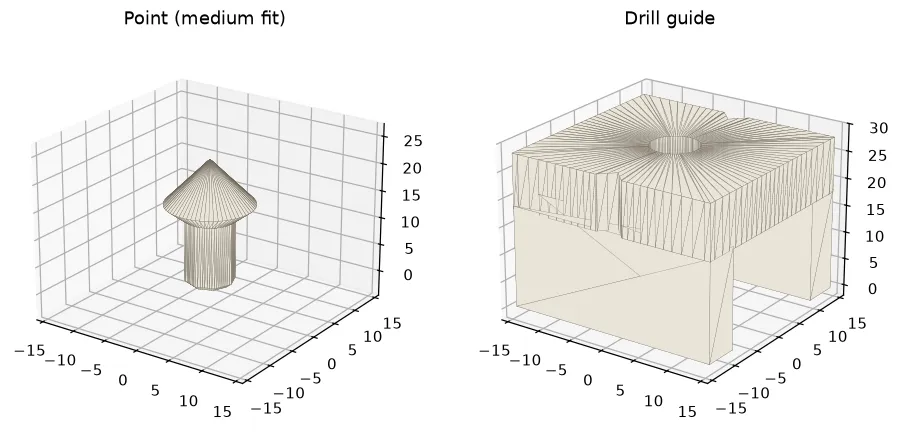
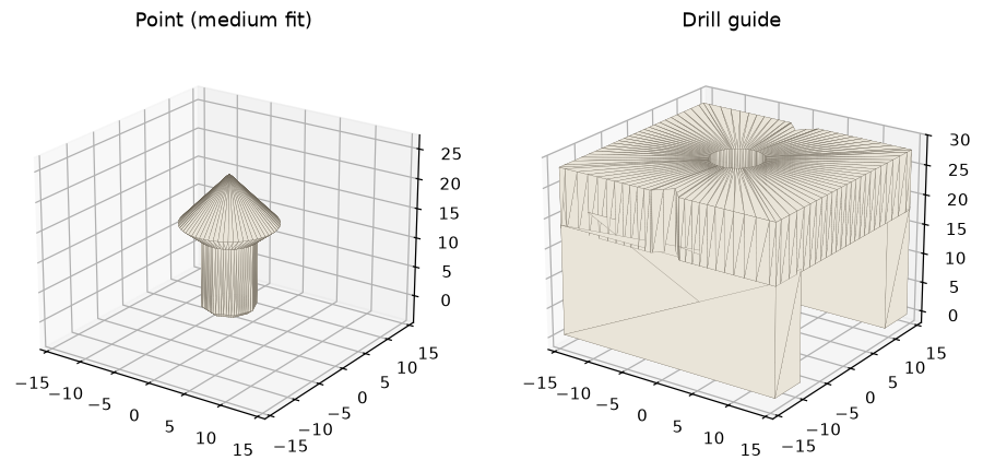
The printable point is a cone above a collar, with a peg that presses into a drilled hole in the top edge of an arm. The supplied medium, tight and loose versions let you test the fit in your plywood. Start with a scrap arm and one of each size before printing the full batch.
Each 46-inch arm has four points: 3 and 15 inches from each end, equivalent to 8 and 20 inches from its center. Across 34 arms, that is 136 points. The drill guide straddles the arm to help center the holes; its fit is based on the measured 0.703-inch plywood. The design notes use a 1/4-inch drill bit and a 14 mm hole depth into the wood. Check the actual guide and peg fit before drilling the complete set.
The draft printing starting point is PLA, 0.2 mm layers, three walls and 30% infill, peg-down; print the guide legs-down. These points reduce contact area. Whether they leave an acceptable mark in a particular paint or stain still needs a real finish test.
Assembly plan
See each assembly step in 3D. New parts are highlighted as they move into place. This draft demonstration omits fasteners and housing cuts.
Five steps, from the first arm fit-test to the empty rack. Start the demo to rotate and inspect each stage.
- Cut the frame members and fit-test an arm in a housing. Keep the thicker arms for the bottom two levels.
- Glue and screw the arms into the upright housings, keeping each arm square. Assemble the second upright the same way.
- Join the uprights with the three stretchers, checking the whole assembly for square before the glue sets.
- Assemble the base, attach its locking casters, and connect the frame and gussets to the base.
- Fit the printed points, lock the casters and check the empty rack for stability before trying scrap parts.
The first build will establish fit, stiffness, stability and usable clearances. There is no verified load rating yet. Keep any trial loads low and balanced, and test with scrap before trusting fresh project parts to the rack.
Plans and downloads
These are draft design files for inspection and fit testing. Use the dimension notes with the layouts; the 3D model is an illustration, not a machining reference.
- Dimension notes and upright housing positions
- Plywood arms and gussets — DXF · layout preview — PNG
- Upright housings — DXF · layout preview — PNG
- Contact point — medium fit STL · tight fit STL · loose fit STL
- Drill guide — STL · point and guide preview — PNG
Next: the first build
The next step is cutting and assembling the DIY panel drying rack. I'll follow up with build photos, any changes needed, the actual materials bill, and what happens when the rack meets its first batch of painted plywood. For now, you can explore the design and see exactly what I'm planning to build.